Acoustic experiments on not hearing the shape of a drum
Can you hear the shape of a drum? This long-standing question in mathematics was popularized by Mark Kac in 1965. It was resolved in 1992 when Carolyn Gordon, David Webb, and Scott Wolpert presented drums with different shapes but the same resonances.

When I learned about the Gordon, Webb, and Wolpert (GWW) result, I thought it would be an interesting project to build the drums and compare the resonances. A physical experiment demonstrating the GWW result had been done by S. Sridhar and A. Kudrolli, but it examined metallic enclosures under the influence of electromagnetic waves. I thought it would be fun to construct acoustic drums in the spirit of Mark Kac's famous question. Holograms could be used to locate and image the resonances.
The original GWW drums are somewhat complicated, making them difficult to build. Fortunately, S. J. Chapman showed that the GWW drums are examples from a class of isospectral drums which also includes the simpler drums in Figure 2.

Building the acoustic drums
Each acoustic drum in this experiment is a thin metallic membrane sandwiched between two thick aluminum plates which have one of the patterns of Figure 2 cut out of them. Figure 3 shows one of the drums.

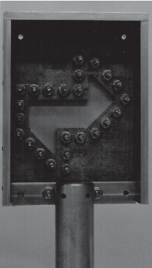
Strictly speaking, a drum with a rigid membrane behaves differently than one with an ideal membrane. However, a Taylor series argument shows that a rigid plate is similar to an ideal membrane if the displacement of the plate from its rest position is very small: Suppose we pick a point on the surface of the membrane and displace it by a small amount, u. There is a restoring force associated with this displacement, call it F(u). F(u) can be expressed as a Taylor seriesF(u) = ∑<sub>k=0</sub><sup>∞</sup> [(F<sup>(k)</sup>(0))/k!] u<sup>k</sup>For a small displacement, a good approximation is F(u) = Cu where C is simply a constant. So, if the displacement is small enough, all membranes behave similarly.
I constructed the drums at the same time to allow for the most consistency between them. Four 4"×5" rectangles (two for each drum) were cut from 0.25" aluminum. The scale of the drums is such that a triangle and its reflection form a one-inch square. The pattern was milled out of each. The cutting was very accurate except for some acute angles, which have radius of 1/16". 25 holes were drilled about the perimeter of the pattern to accommodate bolts that secure the perimeter of the membrane. The frame was reinforced with 2" wide strips of 0.25" aluminum perpendicular to plane of the frame on the top and sides by tapping into both the front and back of the frame. A supporting bar on the back was also tapped into these strips. The entire drum assemble was painted white. For time-average images at the resonances, the frame surrounding the membrane was covered with black tape to reduce reflections.
The membrane was thin aluminum sheet metal, cut into rectangles that were slightly larger than the frame. Oversized holes were drilled that corresponded to the bolt holes in the frame. These holes were deburred and very slightly countersunk, so the frame clamped down on the rectangle uniformly. The two membranes were annealed in a small oven.
WARNING: These drums required very high-volume levels to drive. I believe that such volume levels are unhealthy and could cause ear damage. Ear protection (for example, earmuffs or earplugs) helps but may not be enough. If you plan to replicate this experiment, you should use a more flexible membrane material that would require less volume to drive.
Optical setup
Holographic interferometry is useful for studying resonances. A good reference is Holographic and Speckle Interferometry by R. Jones and C. Wykes (Cambridge U. Press, 1983). A standard split-beam setup was used.
The components were arranged on an optical table, except for the speaker, which was placed directly behind the drum but supported by a boom from above to isolate its motion from the optics.
Two types of holographic interferometry were used: real-time holographic interferometry to find the resonances and time-average holographic interferometry to photograph the modes.
Real-time holographic interferometry is a technique that is commonly used to study slow displacements and stresses of an object. First, a hologram is taken of a stationary object. The holographic plate is developed and replaced exactly — that is, within λ / 4, where λ is the wavelength of the laser light — where it was during the exposure. (A plateholder with six points of contact to suspend the plate was constructed and used; information about it can be found in Jones and Wykes.) If the same reference beam is used to view the image and the object remains exactly where it was during the exposure, the two images coincide, and only constructive interference occurs. If the object is slightly displaced, then light from the two images no longer perfectly coincides and interference occurs at the viewing plane, forming fringes. These fringes can be observed to change in real time with changing displacements of the object. Resonances can be identified by noting the frequencies at which the fringes disappear due to rapid movement.
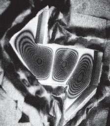
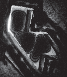
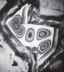
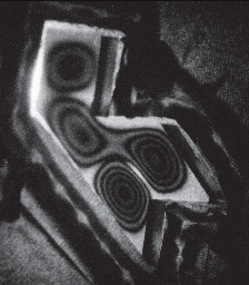
Time-average holographic interferometry is designed for the study of objects which vibrate quickly relative to the length of the exposure. If the object facing the holographic plate experiences a harmonic displacement normal to the surface, fringes form which follow the square of the zero order Bessel function. This provides a contour map of the movement of the vibrating surface. An example of the time-average holograms collected is given in Figure 4.

How well did it work?
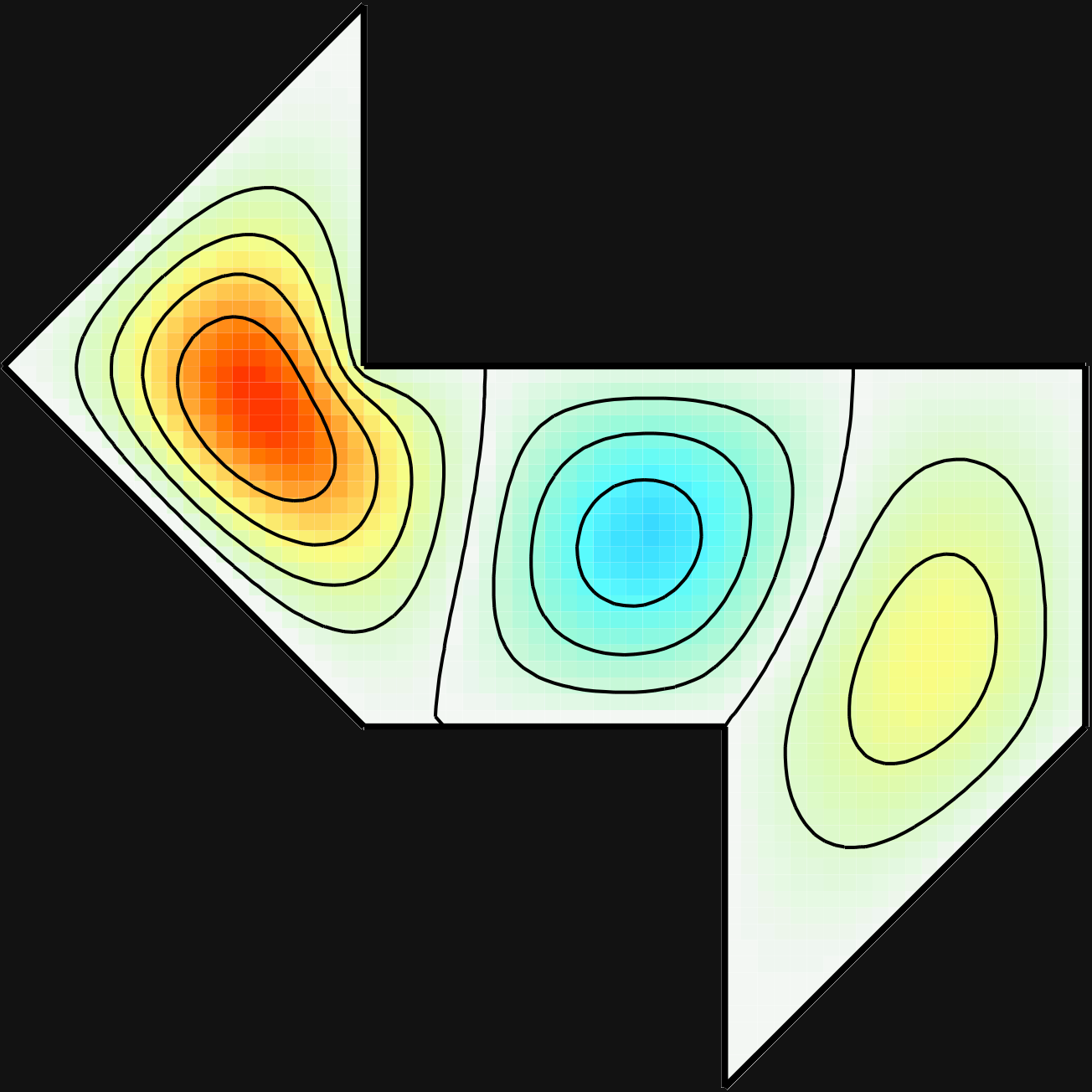
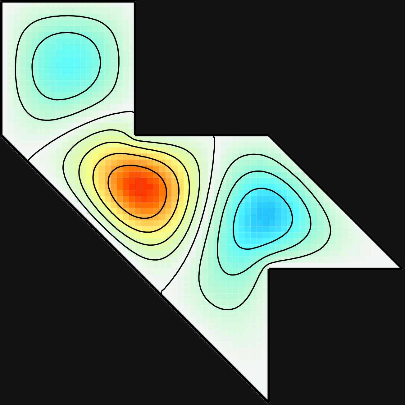
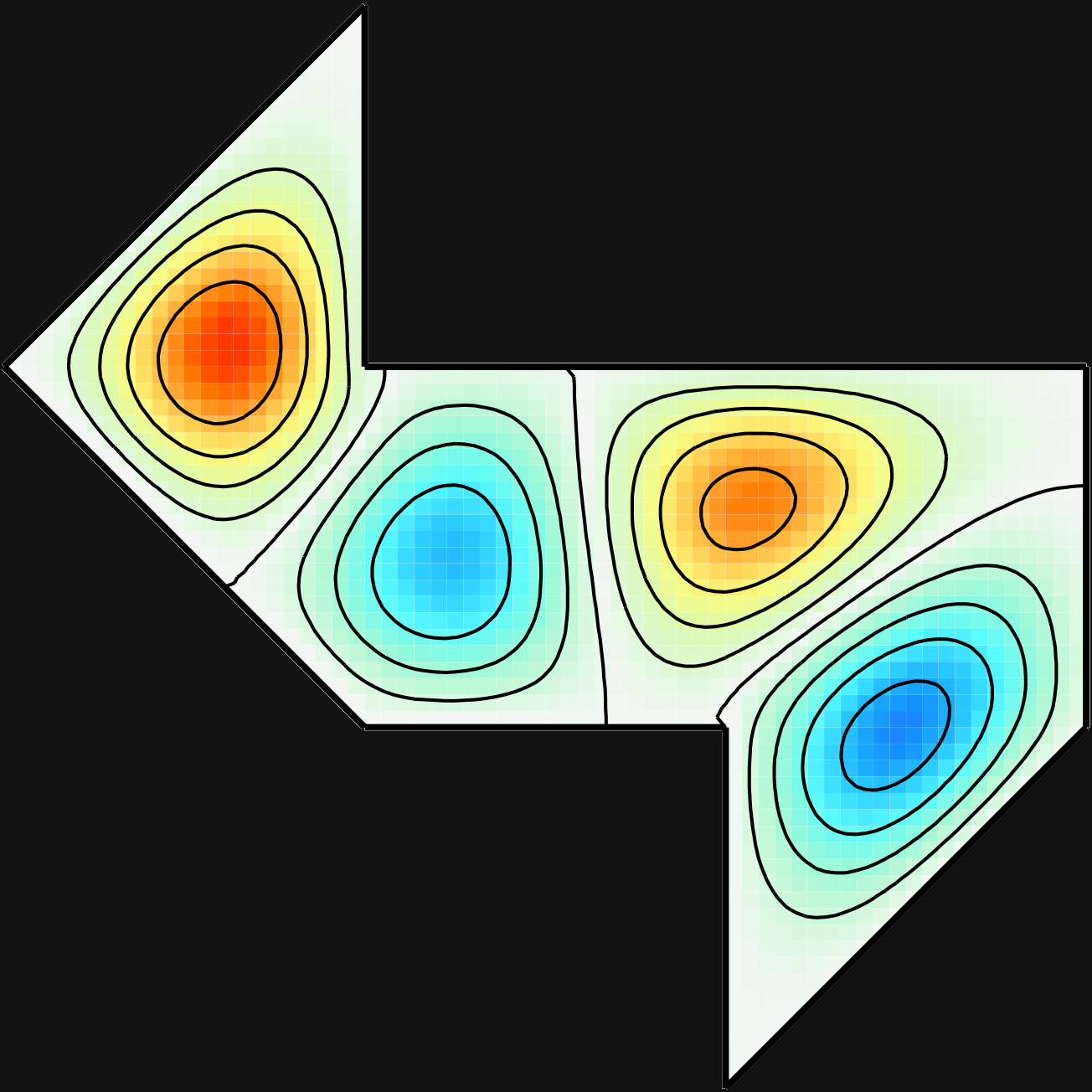
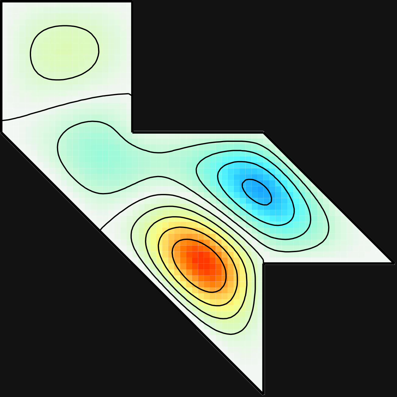
I observed more resonances than Sridhar and Kudrolli did, particularly at lower frequencies. These redundant resonances seemed to be drum resonances coupled with stand resonances. (In some cases, the time-average holography contour lines even cut through the boundary of the drum, clearly indicating that the stand was vibrating.) To determine the pure resonances, it was necessary to consult modes calculated numerically by Toby Driscoll. As an illustration, the time-average images of modes 3 and 4 are given in Figures 5 and 6, respectively, along with the numerical results of Driscoll. The holographic images resemble Driscoll's computational results very closely. The resonances are listed in Table 1.
| Number | Left | Right | Difference |
|---|---|---|---|
| 1 | 5.0654 | 4.5060 | 12% |
| 2 | 6.6009 | 6.5685 | 0% |
| 3 | 8.5023 | 8.2110 | 3% |
| 4 | 10.1982 | 9.8879 | 3% |
| 5 | 10.8583 | 10.3320 | 5% |
| 6 | 12.1340 | 12.7880 | 5% |
With the exception of the first entry, the resonances of the drums match reasonably well. The first resonance might involve a coupled resonance. Perhaps it would be possible to understand the effect of coupled resonances by creating a second set of drums identical in shape but with a very different type of assembly. Images taken with two different assemblies would enable one to pinpoint coupled modes because they would not be common to both stands, whereas the true resonances of the drum would be common to both types of assemblies. It is also possible that resonances would match better with more precise manufacturing.
Acknowledgments
Thanks to Alma Zook and Jon Eggert for introducing me to the GWW result and providing useful suggestions. Thanks to Toby Driscoll for providing his numerical results.